Drilling Fluid Circulation Process
Schematic diagram of drilling fluid circulation process

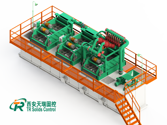
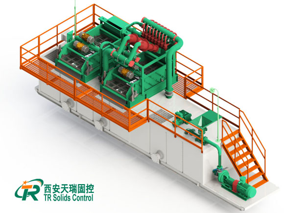
The drilling fluid from the wellhead flows into the distributor through a pipeline, and is separately or simultaneously transported to two vibrating screens. After treatment, the drilling fluid enters the sinking silo and enters the desanding silo through the aqueduct. The drilling fluid passes through the aqueduct to the mud removal bin except for the drilling fluid in the sand pump suction sand removal bin. The drilling fluid passes through the aqueduct into the centrifuge compartment except for the drilling fluid in the mud pump suction chamber. The vertical liquid pump of centrifuge inhaled the drilling fluid of centrifugal chamber, and the drilling fluid entered the liquid storage tank through the aqueduct. The drilling fluid is pumped into the wellhead through the pipeline. This completes the circulation process of drilling fluid.
Schematic diagram of drilling fluid weighting process

Schematic diagram of drilling fluid weighting process
The weighting process of drilling fluid is an auxiliary process in the solid control system of drilling fluid. By adding barite and other components into the drilling fluid, the density of drilling fluid can be increased and the wellbore stability can be maintained to meet the drilling requirements. The weighting pump of 4# tank can directly inhale the drilling fluid in the drug mixing bin, the weighting mixing bin and the reserve bin through the weighting suction pipeline. After the weighting treatment by the weighting funnel, the weighting discharge pipeline can be transported to the tanks of 3# tank and 4# tank. Thus the drilling fluid weighting process is completed.
Schematic diagram of drilling fluid dosing process

Drilling fluid dosing process is to add chemical treatment agent to the drilling fluid, using the principle of chemical sedimentation, remove harmful solid components to improve drilling fluid performance, improve wellbore stability, and improve the penetration rate. The upper part of the medicine mixing bin of 4# tank is equipped with a medicine filling tank. The medicine enters the medicine mixing bin through pipeline from the medicine filling tank. After mixing by agitator, it is transported to the wellhead through the suction pipeline by the drilling pump. It can also be sucked by the weighting pump through the weighting suction pipeline and transported to the 1# tank supply bin, 2# tank and 3# tank through the mud gun pipeline. This completes the process of drilling fluid dosing.
Schematic diagram of drilling fluid replenishment process

Drilling fluid replenishment process is to ensure the stability of the wellbore by supplying drilling fluid to the wellbore during the lifting of the drilling tool. The left end of 1# tank is equipped with a supply bin. The supply pump sucks drilling fluid from the supply bin and conveys it to the wellhead through the discharge pipeline. The drilling fluid returned from the wellhead is controlled by a distributor branch valve and enters the supply bin. The drilling fluid in the replenishment silo can also be sucked into the storage silo by a heavy pump and transported to the replenishment silo via a mud gun pipeline. This completes the drilling fluid replenishment process.
Contact us
Email: sunny@trsolidscontrol.com
WhatsApp:+86 13201722103


Leave a Reply